
4558 Ic Subwoofer Circuit Circuit Diagram
The IC 4558 is a popular operational amplifier (op-amp) used in audio applications and is commonly used in subwoofer circuits. The layout of the subwoofer IC 4558 is an important factor in achieving high-quality sound reproduction. The layout of the IC affects the performance of the subwoofer, and a well-designed layout can significantly.

4558 Ic Circuit Diagram
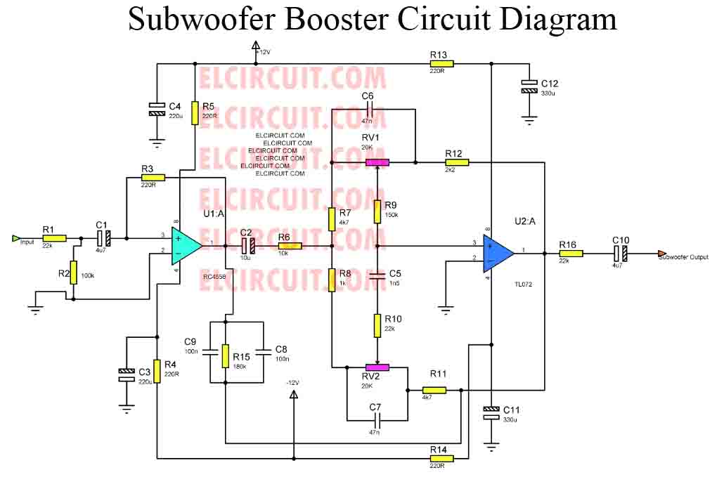
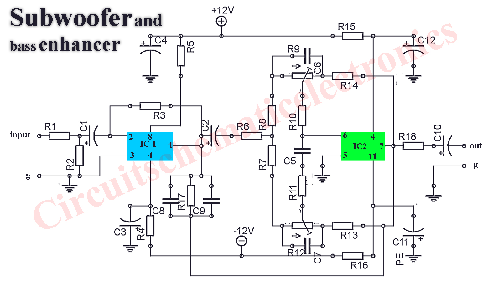
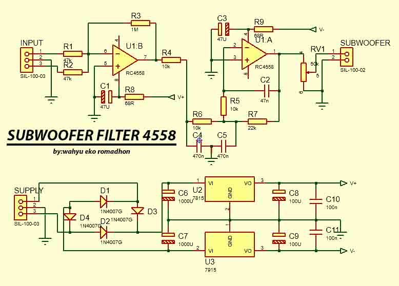
The 4558 IC subwoofer bass booster low pass filter circuit uses a combination of resistor-capacitor networks, op-amps, and inductors to filter and enhance low-frequency sounds. The low-pass filter network filters out the high-frequency signals, leaving only the low-frequency sounds.

4558 Ic Circuit Diagram
Explanation of Subwoofer Amplifier Circuit TDA2030 JRC4558. The TDA2030 is a monolithic integrated circuit in a Pentawatt package that offers high-quality audio reproduction with low distortion and noise. It operates on a wide range of power supplies and delivers a maximum output power of 14W. The TDA2030 has excellent thermal and short-circuit.

4558 Ic Audio Equalizer Circuit Diagrams Circuit Diagram
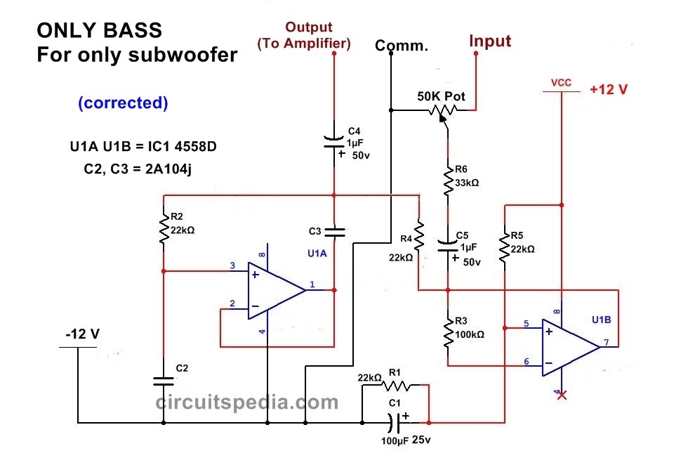
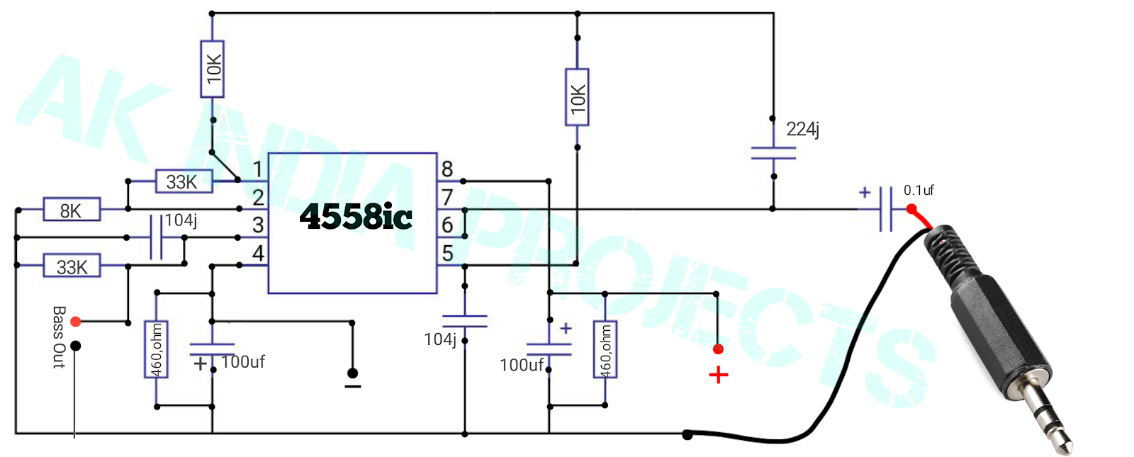
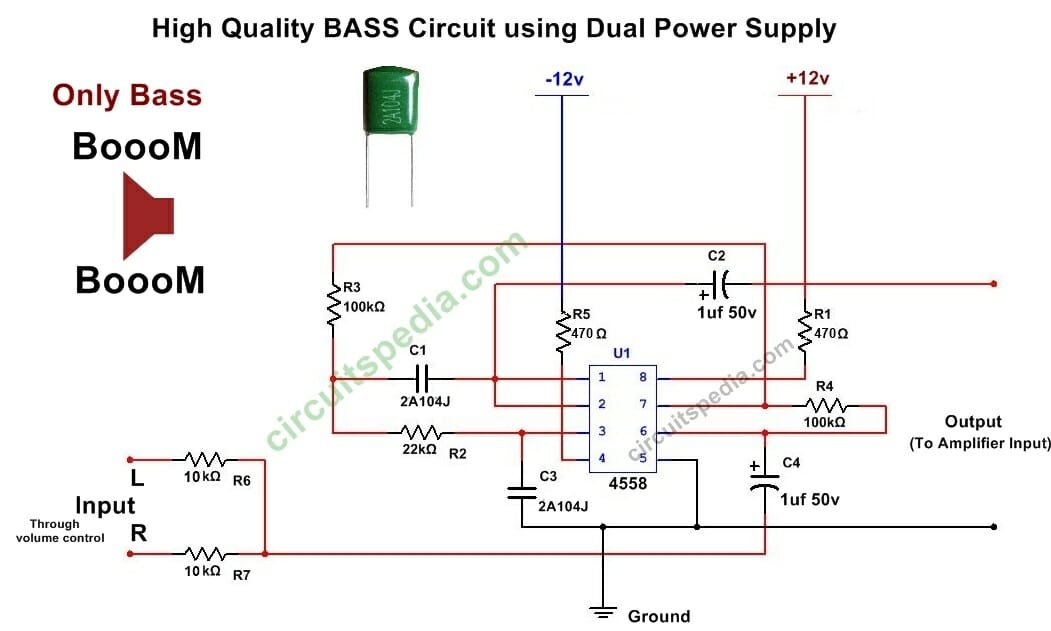
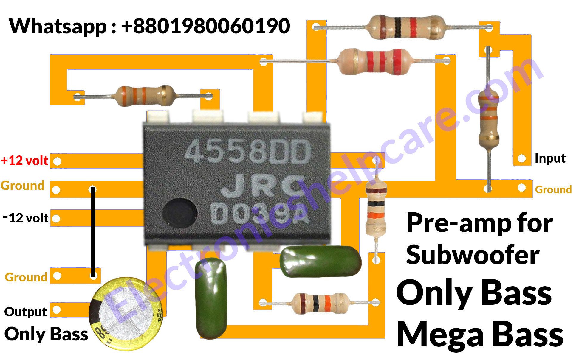
The IC njm4558 subwoofer bass boost circuit. 4558 is an op-amp which is most commonly using in the audio amplifier. The ic is available in an old subwoofer amplifier and stereo amplifier board. njm4558 ic. The ic is inbuilt with two op-amps. The ic will able to handle the low audio frequency ranges. The operation voltage of this ic is 5v to 18v.

Full bass 4558 ic subwoofer speakers control (100 Working) YouTube
The 4558 IC operates on a supply voltage range of ±4V to ±18V and provides excellent signal-to-noise ratio, low noise output, and high common-mode rejection ratio. Due to its versatile characteristics, this IC can be used for various purposes, including audio pre-amplification and tone control circuits. TDA2030 Subwoofer Amplifier Circuit.

Pin on ic4558
Circuit Diagram Components Required What is a Low Pass Filter? A low-pass filter (LPF) circuit is a filter that passes signals with a frequency lower than a selected cut-off frequency and attenuates signals with frequencies higher than the cut-off frequency. The exact frequency response of the filter depends on the filter design.
ic 4558 Subwoofer Bass Booster Circuit diagram , bass circuit for woofer
In this video, we are going to show you making a bass booster circuit using 4558 IC. If you need extra bass, then you can apply this circuit. This circuit ha.
Subwoofer 4558 Ic Bass Treble Circuit Diagram / How to make bass
The 4558 IC Subwoofer Circuit 12v has a frequency response of 20 Hz to 200 kHz, making it ideal for any kind of music, from classical to heavy metal. It also has an adjustable gain control that lets you fine-tune your sound to suit your preferences. And best of all, it comes with a built-in noise filter, ensuring your audio is free of unwanted.
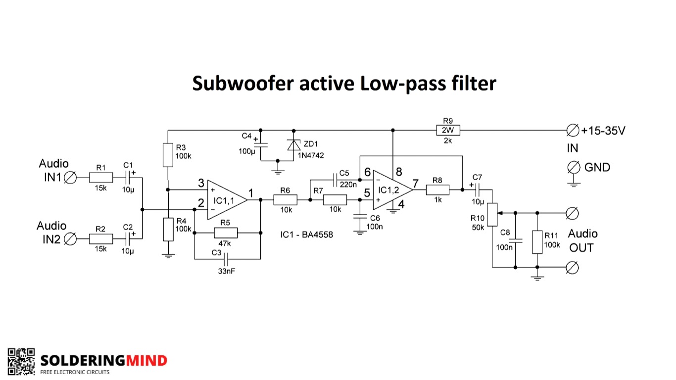
Low pass filter circuits using 4558 IC Soldering Mind
Low Pass Filter for Subwoofer With 4558D IC: In this project I will show you how you can make a Low Pass Filter with 4558D IC for Subwoofer.. Connect this pin with ground and your circuit will be turn on and works. Plz replay if your problem solved. Thanks . 0. kh025104. Question 4 years ago on Step 3. Answer Upvote. sir 4558 low pass filter.
4558 Ic Subwoofer Circuit Diagram Pdf Home Wiring Diagram
The 4558 IC is an excellent Bass booster and it helps to increase extra bass without any disturbance. This bass booster circuit reduces the audio frequency to a lower value. The actual concept of the bass booster is for low-frequency sounds. If you want extra bass then you can use this circuit. This circuit doesn't give a treble sound.
how to make subwoofer circuit diagram Electronics Help Care
Pin Off 4558d Ic|4558d subwoofer circuit diagram|4558d bass circuit|Mr Electro #4558 #4558d_bass_circuit#mrelectro 4558 ic bass circuit4558 ic subwoofer ci.

Powerful Low Pass Filter Using 4558ic Simple 12V Low Pass Filter
A low pass filter circuit Bass Booster is an essential component in audio systems that enhances the bass frequencies of an audio signal. The JRC4558 IC, an integrated circuit, is widely used in low pass filter circuits due to its superior performance and versatility. This circuit is known for its ability to isolate low-frequency sounds and.
4558 Circuit Diagram
This is The Circuit Only For BASS Booster using 4558 ic, By using this bass circuit for woofer the audio is bass Boosted . This circuit Give Clear Bass Without Any Disturbance. If You Need to extra bass Then you can apply this circuit Bass Control circuit. So Only Give The Output Of This to Bass Speaker (Woofer) only.
Ic 4558 Preamp Circuit Diagram Pdf Wiring Diagram
4558 ic subwoofer circuit || low pass filter Board connection || Electronics verma Electronics Verma 288K subscribers Join Subscribe 499 Save 22K views 10 months ago #lowpassfilter.
Engenharia Circuito Filtro de Subwoofer 4558 complete Regulated Power
In this video how to build a simple, high-quality bass booster circuit for a subwoofer with IC 4558D. This circuit can be connected to many other amplifiers.

How to make bass boosted circuit ic 4558 for subwoofer YouTube
The circuit that I publish, is a circuit of modules that use the subwoofer amplifier ic op-amp 4558 which acts as a reinforcement of bass tones (subwoofer) assisted of it's by the workings of some supporting components such as resistors, capacitors.